Shape Importer Tutorial
Creating Shapes for StarLogo TNG
Introduction
StarLogo TNG renders agents with two types of shapes. Agents can either have OBJ file shapes or MD3 file shapes. OBJ file format is standard in most 3D graphics authoring toolkits. MD3 files were created by ID Software for the Quake 3 game engine. StarLogo TNG can import Quake 3 models in PK3 format and extract the MD3 models. There are tradeoffs with either type of shape; OBJ shapes are easy to render and can change color, but MD3 models have animation and textures. Available Quake 3 models may not suit your StarLogo TNG project. With a 3D modeling and animation tool, an MD3 exporter, and this tutorial, you should be equipped to create your own custom shapes for Starlogo TNG.
Understanding the MD3 Model Structure
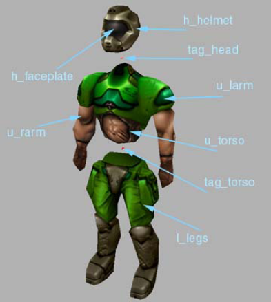
Quake 3 models are split into three MD3 models: head, upper, and lower. With separate models, the Quake 3 game engine allows the legs to be facing in the direction of movement while the head and torso are facing other directions. If the model was not divided, a set of leg animations would be necessary for every possible direction of the torso and head.
Each model is drawn relative to its tag. In StarLogo TNG, each model is rendered from the bottom up. The legs are positioned relative to an implicit floor tag, aptly named tag_floor. The legs MD3 model generally contains the torso tag, tag_torso. StarLogo TNG then positions the torso relative to the torso tag. The torso model has the tag_head and tag_weapon tags. Finally, the head model is placed at the head tag.
Animations
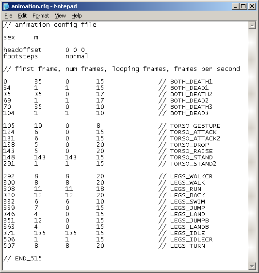
An MD3 file consists of the locations, normals, and texture coordinates of every vertex for every frame. To specify the frames that correspond to appropriate animations, every MD3 shape in StarLogo TNG has an accompanying animation.cfg file. Of the animations listed in the animation configuration file, StarLogo TNG (and Quake 3) only uses the first 25. An animation is defined by the starting frame, length in frames, number of frames to repeat, and the frame rate. It is not necessary that the MD3 file be animated in the order listed in the animation configuration file, but each line of the configuration file has to be in order. When modeling a shape, it is helpful to the keep the animations in mind, as it is usually difficult to edit the 3D mesh of a model after animation.
Quake 3 Compatibility
If you plan to reuse the model for Quake 3, there are a few more constraints to maintain. First, Quake 3 requires everything to be zipped in a PK3 file with a proper file structure. See a Quake 3 modeling tutorial for details. Also, Quake 3 reserves certain frames for the attack, reload, and change weapons animations.
124 6 0 15 // TORSO_ATTACK
131 6 0 15 // TORSO_ATTACK2
138 5 0 20 // TORSO_DROP
143 5 0 20 // TORSO_RAISE
Although StarLogo TNG ignores the tag_weapon tag, it must be present in Quake 3 models. Quake 3 PK3 files have three directories: models, scripts, and sound. To be a valid model, all 3D information has to be in models/players/<name>/. If the model requires a custom shader, it belongs in the scripts folder. Custom sounds go in sound/player/<name>.
Putting it all Together
To see an example, visit the
Bear creation
tutorial.
Creating the Skin Meshes
A StarLogo TNG shape is typically made as one legs mesh or in the Quake 3 style of three meshes. The next paragraph of this section describes the legs only approach and the subsequent paragraph explains the steps for the three meshes.
Although tag_floor is never seen, it exists at 24 units below the x-y plane, facing in the positive x direction. For your model to be standing on the ground in the forward direction, its feet must be standing on the z = -24 plane and facing the positive x direction. A standard humanoid shape is usually tall enough to break the z = 0 plane, but StarLogo TNG can scale a shape in any direction. If you create a shape with a single lower mesh, you can ignore all tags unless you intend on importing the model to Quake 3.
When creating a model using head, upper, and lower meshes (or groups of meshes), it is suggested that the three groups of meshes are created together and separated after animation. Just like with a single mesh, the lower mesh should be standing on the z = -24 plane facing in the positive x direction. The upper mesh should sit on top of the legs, and usually overlaps at the waist to give the illusion of continuity during animation. The head mesh then sits atop the upper mesh.
Everything that will be considered part of the lower mesh or group of meshes should have “l_” as the first two letters of the name. Similarly, everything upper should have “u_” and everything that’s part of the head should have “h_”.
Shape Qualities
The speed with which a shape is rendered is largely dependent upon the number of vertices in the mesh or meshes. A Quake 3 usually has less than 1024 vertices, but should never have more than 4096. StarLogo TNG calculates distance of an agent from the camera and renders lower quality shapes for larger distances. To create lower quality shapes, copy the shape and lower the vertex count of the copies. Your workspace may feel cluttered, but to prevent redundant work, the meshes are separated after the animation. StarLogo TNG searches for a medium and low quality version when a shape is loaded. The medium quality shape has “_1” in the filename and low has “_2”. Methods of lowering the number of vertices include vertex welding, collapsing edges, and collapsing faces. The filenames and file structure is explained in greater detail in the exporting section. You should create lower quality shapes immediately after modeling the original versions because it is exceedingly difficult to lower the vertex count after binding meshes to bones, adding textures, and animating. If a shape is expected to be used hundreds of times in a StarLogo TNG project, it is important that it have as few vertices as possible to maintain graphics performance. This is especially true for the low quality shape, as it is drawn the most frequently if agents are spread across SpaceLand.
Binding the Mesh to Bones
Not all shapes need bones, but it makes animation easier for things that use some sort of skin deformation. For example, the rigid and segmented elbow of a robotic arm can be animated directly, while the flexible and continuous elbow of a person would most likely use bones. If you are creating a model that will be animated without bones, this section is irrelevant.
Once bones have been created for the whole shape, they can be bound to the mesh or meshes. Also, tags should be bound to the bones so that they move with the animation. The torso tag should be bound to the pelvis or base of the back, the weapon tag bound to a hand, and the head tag bound to the top of the neck. Animating these tags ensure the appropriate mesh is drawn at the right place every frame.
Animating
Most Quake 3 models are animated in the order specified in the animation configuration file, but no order is necessary. Each animation has a start frame and duration; as long as the animations are listed in order, they can start and end at any frame in the file. Quake 3 requires every animation to be present. StarLogo TNG loads the first 25 animations in the configuration file. Currently, StarLogo TNG only uses the standing (LEGS IDLE) and walking (LEGS WALK) animations. As StarLogo TNG evolves, other animations will become available. It is suggested that you animate every possible animation and specify it in the configuration file.
Texturing
In addition to the XYZ coordinates, every vertex has UV texture coordinates. Methods for editing UV coordinates are specific to the modeling program. Textures can be a composition of the images for each face or they can be a tile-able image and applied to all faces. For a texture to fit nicely on a graphics card, it must be square and each side’s length a power of 2. Textures are usually 256x256, but should never exceed 1024x1024. StarLogo TNG accepts textures in TGA, PNG, JPG, and GIF formats. For StarLogo TNG to recognize the texture, it must have 32 bit depth. This means that a pixel’s red, green, blue, and alpha components each use 8 bits. In other words, 32-bit depth means the texture has millions (16,777,216) of colors defined by the 24 bits of RGB. Though the texture can be completely opaque, it must have an alpha channel to complete the 32 bits.
Exporting and Files
Once you have modeled, animated, and textured the StarLogo TNG shape, copy the file for as many shape qualities and mesh groups that you have. For example, if you only have one shape quality and one lower mesh, you do not need to make any copies. If you have all three mesh groups and all three qualities, you will need eight copies. Each copy should only have a single quality and a single mesh group: lower, upper, or head. Once each group of meshes and shape quality has been separated, they can be exported to MD3 files. The mesh will be the title of the MD3 file. If the quality is medium, the filename should end in “_1” and if the quality is low, the title should end in “_2”.
A group of meshes is not sufficient to describe a StarLogo TNG shape. Each shape also needs a skin. The first skin is usually named the default skin. The first file necessary for StarLogo TNG to recognize the skin is the icon. A default skin’s icon is named “default_icon.png”. Likewise, any skin’s icon filename is the skin name followed by “_icon”. The meshes have UV coordinates, but the vertex information does not carry information about the actual texture. The MD3 files require the texture image file and a SKIN file to render textures. A SKIN file is a text file that specifies the texture image files belong to which mesh. For example, a single line in a SKIN file may read, “u_torso, /texture.png”. This line states that the upper mesh named u_torso will use its UV coordinates and the texture image texture.png for its texture. A SKIN file has the same name as the associated MD3 file but followed by an underscore and the skin name. For example, the SKIN file for the default skin for a medium quality lower MD3 file would be named, “lower_1_default.skin”.
The last files necessary are the animation configuration files. A different file is necessary for each shape quality so that lower quality shapes can have fewer frames. An example file for a low quality shape is “animation_2.cfg”. It is suggested that you modify an existing animation configuration file to ensure you have all of the animations in the correct order.
- Login to post comments